Electrical
Shielding
Q: How do computer chassis help control and reduce coupling? Does the composition or material have an effect?
A well-built chassis will not only reduce outside interference from reaching sensitive computer components it will also reduce the noise radiating out. Most materials will have some level of resistance however some may only resist high frequencies whereas some both low and high.
Desktop chassis on the market today use a mix of materials such as tempered glass, plastic, cold-rolled steel and/or aluminum. These materials may reduce some higher frequency noise but not lower frequencies which is more commonly associated with alternating current from power lines, transformers and supply.
For more information on chassis shilelding, material resistance, and real-world case measurement. See findings and analysis below.
Findings and Analysis
Having researched the current market of desktop chassis and composition it was clear most vendors cater to those interested in the presentation of unique designs and lighting effects instead of environmental conditions or treating computers as scientific devices. This made sense given the current market so no fault to them during my search for an ideal chassis. I contacted the support of the top 10 desktop chassis vendors and found that none would meet the specifications below, except one potentially but it currently remains untested.
Key Factors for Chassis Selection
- Ventilation and cooling
- Materials resistance to environment
- Thickness
- Type(s) of materials
- Fully enclosed with the exception of ventilation
- Limited air gaps in relation to interfering frequency or in corners/joins
- If air gaps are a concern you can get EMI gaskets
- Compartmentalization e.g. internal noise and shielding
Industrial Grade Server Chassis Specifications
- SGCC (Galvanized Steel)
- 1mm or thicker
- Fully enclosed (all sides) in SGCC except where required for ventilation
Server Grade Chassis Example - mATX/ATX Compatible
- Rosewill RSV-R4100 4U Rackmount Server Case
Potential Desktop Chassis Candidate
- Antec P7 Silent (0.6 mm SGCC + Plastic)
- Material but not thickness
- Plastic is used on the faceplate but behind faceplate is SGCC
- https://antec.com/product/case/p7-silent.php
My Rosewill RSV-R4100 4U Rackmount Server Case Shielding Measurements
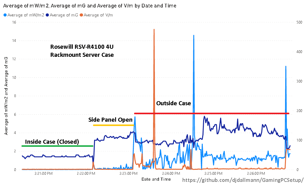 Note: These measurements are specific to my environment and are for demonstration purposes only.
Magnetic Field Shielding Demonstrations (Multiple Materials)
-
YouTube Channel - LearnEMC : Low-Frequency Magnetic Field Shielding Demonstration
-
YouTube Channel - LearnEMC : High-Frequency Magnetic Field Shielding Demonstration
Radio Frequency Interference
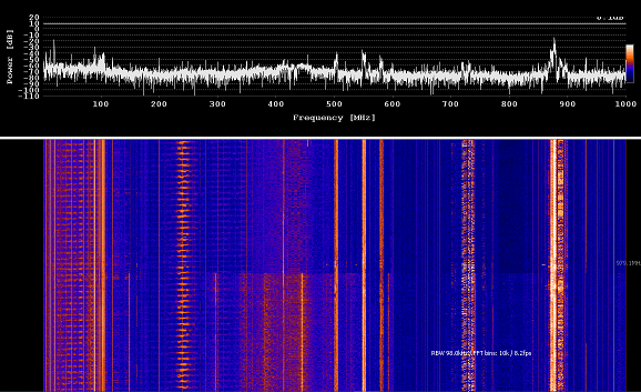
Q: What types of near field radio frequencies do monitors and DVI cables create? Does the color or activity on screen change the radiated emissions?
An LCD monitor may radiate different ranges of near field emissions based on serveral different factors such as the colors displayed and monitors refresh rate, during the few brief experiments it was found that a Benq GL2450 60hz monitor may radiate in the range of 150-800MHz with stronger signals at 150, 280-380, 450 and 590MHz.
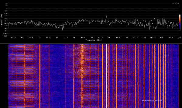
The display cable itself generates frequencies more notably at 82.5 to 84.5MHz depending on the monitors activity, if no active content is being rendered the emissions are not as pronounced similarly as when a single ferrite is applied. See findings and analysis for more information.
Findings and Analysis
-
Monitor: Benq GL2450 TN Panel
-
Benq GL2450 - On vs Off, DVI Connected/Disconnected
- DVI Cable - Ferrite On vs Off
Inductive Coupling
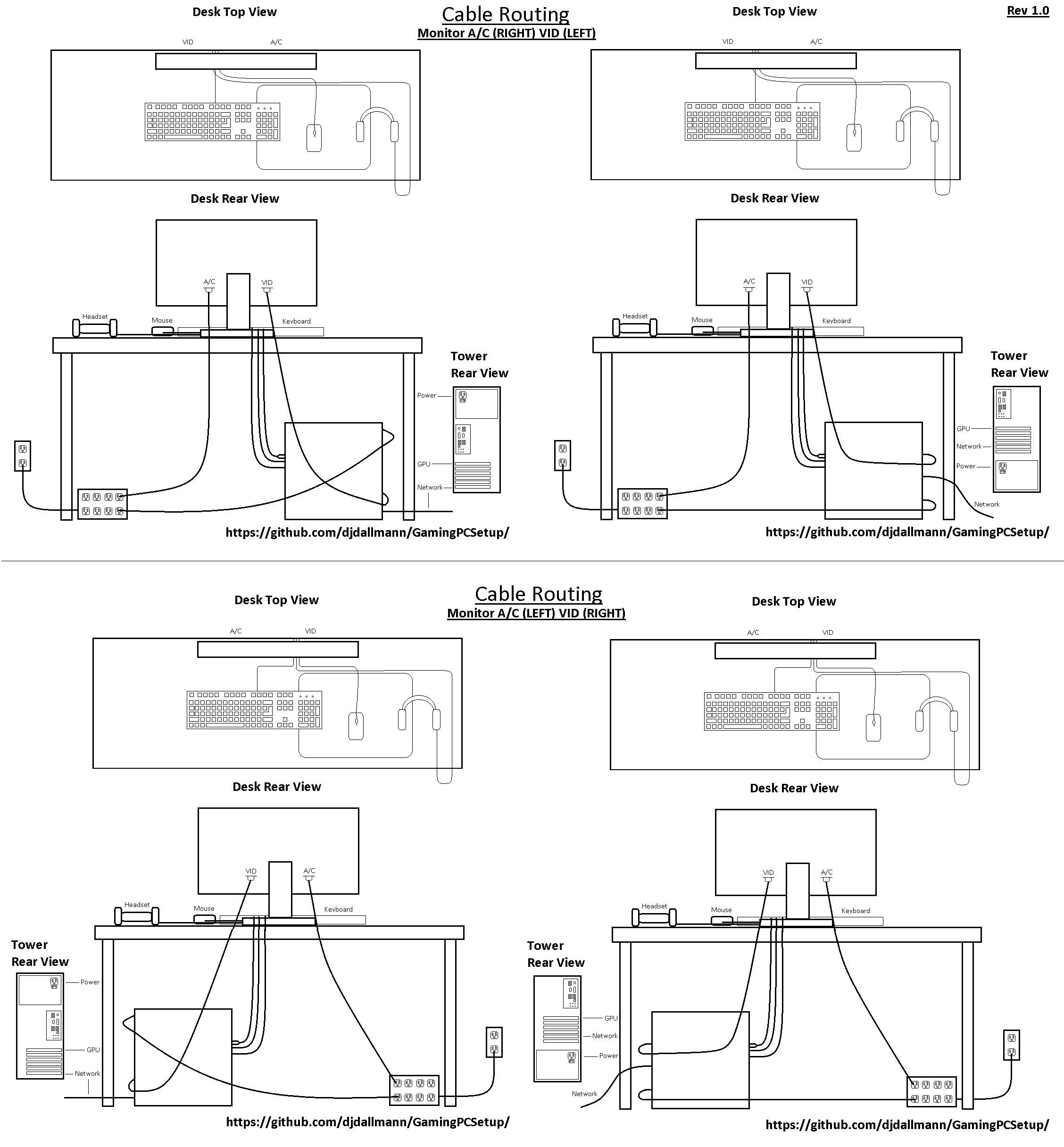
Q: What techniques, physical configuration and cable routing methods may best reduce inductive coupling of data cable, shield and power cables?
Most devices, wiring (e.g. single, twisted and non-twisted pair), cable shields and communication protocols generally provide some or no resistance to inductive coupling and interference. All electrical devices both produce and conduct Electromagnetic Interference (EMI) and Radio Frequency Interference (RFI) which may be near field or far field emissions and radiation. The general rule of thumb in reducing inductive coupling is to appropriately shield data and signal lines, filtering or reducing the impedence of interfereing frequencies (e.g. ferrites, chokes, baluns, toroids), and increasing distance from interfering signals through good cable management practices by separating power from data and signal lines. For more details see findings and analysis for further recommendations and diagrams of a low inductive coupling cable configuration.
Findings and Analysis
- Recommendations for low inductive coupling environment
- Avoid adding things such as speaker systems or DACs to your configuration especially if these require separate grounded power sources which may introduce some noise due to the creation of ground current loops between interconnected devices increasing the ground potential between them.
- Disable or remove known wireless radio frequency transmitters such as wifi routers and cell phones from the area/room
- Consider using shielded power and signal lines for noisy environments. The effectiveness of these shields depend on the source and frequency of the interference, surface coverage, material used, number of layers and thickness, and potentially grounding and bonding those shields.
- Separate signal and power lines to reduce induction/conducted emissions, not only consider those in your office/room but the signal lines which traverse the area such as network cables from the service entry point. In most cases the strength of near field radiation/emissions significantly reduces with distance which could be multiple inches or less.
- Power all interconnected devices at common point using a surge protector and/or uninterruptible power supply (UPS).
- Always use a surge protector to reduce impact of transient events to your devices.
- If your devices are impacted from larger sources interference then shielding a single cable may not make significant difference as all or some components are affected and you may have to explore physically moving the system under test to another area or go to greater lengths (potentially expensive) to shield the source of interference.
- Measure and assess the environment for noisy sources using an AM radio (low frequency), software defined radio (low/high frequency and GHz radio spectrum), use both far field and near field antennas (H-Field/E-Field antenna), oscilloscope, and tools that can measure emissions impact, strength and frequency with spectrum analysis.
For public reputable research on these topics see my technical references electrical section for further reading.
Below is a diagram representing a hypothetical ideal low inductive coupling configuration: